Weight sensor amplifier / junction box
The transmitter accurately amplifies the MV signal output by the sensor;
Convert the mechanical quantity into standard current, voltage and digital signal;
Good electromagnetic tolerance and anti-interference ability;
Single channel, four channel, six channel, eight channel and other simultaneous amplifier conditioning;
Two output relays are available;
Product description of strain type pressure transmitter:
重传感器放大器/接线盒(Weight sensor amplifier / junction box)

1、单路普通型变送器(Single channel ordinary transmitter)


变送器将传感器输出的mV信号进行精密放大,将力学量转换成标准电流、电压信号。
The transmitter accurately amplifies the MV signal output by the sensor and converts the mechanical quantity into standard current and voltage signals.
1.体积小,重量轻具有较高的性价比
  Small size, light weight and high cost performance
2.电源浪涌防护,输入反接保护
  Power surge protection and input reverse connection protection
3.多种输出形式可供选择,满足不同用户需求
  A variety of output forms are available to meet the needs of different users
4.接线使用航空插座 5.外壳带安装孔,方便用户的安装
  Use aviation socket for wiring 5 The shell is equipped with mounting holes to facilitate the installation of users


多路普通型变送器(Multi channel ordinary transmitter)


1.除具有普通变送器的特点,还可以降低变频器等产生的谐波干扰。
  In addition to the characteristics of ordinary transmitter, it can also reduce the harmonic interference generated by frequency converter.
2.良好的电磁耐受性(EMS)。
  Good electromagnetic tolerance (EMS).


不锈钢接线盒(Stainless steel junction box)


1.尺寸(四路):185x134x35(mm)
  Size (four-way): 185x134x35 (mm)
2.可选四路、六路、八路等接入方式 
  4-way and 8-way access modes are optional
3.不锈钢外壳,美观耐用,专用密封接头,密封性好 
  Stainless steel shell, beautiful and durable, special sealing joint, good sealing performance
4.采用高精度、低漂移电阻和电位器,保证系统工作精度和稳定性 
  High precision, low drift resistance and potentiometer are adopted to ensure the working accuracy and stability of the system
5.PCB板焊有防浪涌及防感应雷的保护性元器件,可有效防止感应雷和浪涌信号对传感器及仪表的
  The PCB board is welded with protective components against surge and induced lightning, which can effectively prevent the impact of induced lightning and surge signals on sensors and instruments


数字式测控变送器(Digital measurement and control transmitter)


1.采用精密压铸铝外壳,表面喷塑处理。
  It adopts precision die-casting aluminum shell with plastic spraying treatment on the surface.
2.适用于精度等级较高及环境较差的场合使用。
  It is suitable for occasions with high accuracy and poor environment.
3.采样频率:10Hz;具有RS232或RS485通讯功能。
  Sampling frequency: 10Hz; It has RS232 or RS485 communication function.
4.两路继电器输出(常开和常闭均提供)。
  Two relay outputs (both normally open and normally closed).
5.使用蜂鸣器和发光二极管实现声报警、光提示。
  Use buzzer and led to realize audible alarm and optical prompt.
6.采取抗干扰电源设计技术;电压模拟量输出具有短路保护功能。
  Adopt anti-interference power supply design technology; The voltage analog output has the function of short-circuit protection.
7.接线使用接线端子及航空插座,外壳带安装孔。
  Wiring terminals and aviation sockets are used for wiring, and the shell is equipped with mounting holes.
8.使用两个按键进行输出调整,无电位器等模拟调节部件。
  Use two keys to adjust the output without analog adjustment components such as potentiometer.
9.可选配软件进行标定和报警值设定。
  Optional software can be used for calibration and alarm value setting.


轨道式多路数字变送器(Track type multi-channel digital transmitter)


1、变送器可选配一到四路传感器。 
  The transmitter can be equipped with one to four sensors.
2、精度:可达0.05%F?S(一拖四)。 
  Accuracy: up to 0.05% f? S (one for four).
3、采样频率: 10次/秒。 
  Sampling frequency: 10 times / second.
4、通讯口: RS-485,支持标准Modbus RTU通讯协议。 
  Communication port: RS-485, supporting standard Modbus RTU communication protocol.
5、模拟量输出:4-20mA或0-5V/10V。 
  Analog output: 4-20mA or 0-5V / 10V.
6、传感器激励电压:5VDC。 
  Sensor excitation voltage: 5VDC.
7、模块工作电源:12~36VDC。 
  Working power supply of the module: 12 ~ 36VDC.
8、具有总线供电及RS-485通信功能。 
  It has bus power supply and RS-485 communication function.
9、标准DIN导轨安装方式。 
  Standard DIN rail installation.
10、壳体尺寸(带接线端子):115mm×90mm×40mm。 
  Shell size (with terminal): 115mm × 90mm × 40mm。
11、工作温度 -20~70℃。 
  Working temperature: - 20 ~ 70 ℃.
12、采用抗干扰电源设计。 
  Anti interference power supply design is adopted.
13、使用两个按键进行输出调整,无电位器等模拟调节器件。 
  Two keys are used for output adjustment, without analog adjustment devices such as potentiometers.
14、防护等级IP65。 
  Protection grade IP65.
Application fields:
Specification parameter
重传感器放大器/接线盒(Weight sensor amplifier / junction box)

1、单路普通型变送器(Single channel ordinary transmitter)


变送器将传感器输出的mV信号进行精密放大,将力学量转换成标准电流、电压信号。
The transmitter accurately amplifies the MV signal output by the sensor and converts the mechanical quantity into standard current and voltage signals.
1.体积小,重量轻具有较高的性价比
  Small size, light weight and high cost performance
2.电源浪涌防护,输入反接保护
  Power surge protection and input reverse connection protection
3.多种输出形式可供选择,满足不同用户需求
  A variety of output forms are available to meet the needs of different users
4.接线使用航空插座 5.外壳带安装孔,方便用户的安装
  Use aviation socket for wiring 5 The shell is equipped with mounting holes to facilitate the installation of users


多路普通型变送器(Multi channel ordinary transmitter)


1.除具有普通变送器的特点,还可以降低变频器等产生的谐波干扰。
  In addition to the characteristics of ordinary transmitter, it can also reduce the harmonic interference generated by frequency converter.
2.良好的电磁耐受性(EMS)。
  Good electromagnetic tolerance (EMS).


不锈钢接线盒(Stainless steel junction box)


1.尺寸(四路):185x134x35(mm)
  Size (four-way): 185x134x35 (mm)
2.可选四路、六路、八路等接入方式 
  4-way and 8-way access modes are optional
3.不锈钢外壳,美观耐用,专用密封接头,密封性好 
  Stainless steel shell, beautiful and durable, special sealing joint, good sealing performance
4.采用高精度、低漂移电阻和电位器,保证系统工作精度和稳定性 
  High precision, low drift resistance and potentiometer are adopted to ensure the working accuracy and stability of the system
5.PCB板焊有防浪涌及防感应雷的保护性元器件,可有效防止感应雷和浪涌信号对传感器及仪表的
  The PCB board is welded with protective components against surge and induced lightning, which can effectively prevent the impact of induced lightning and surge signals on sensors and instruments


数字式测控变送器(Digital measurement and control transmitter)


1.采用精密压铸铝外壳,表面喷塑处理。
  It adopts precision die-casting aluminum shell with plastic spraying treatment on the surface.
2.适用于精度等级较高及环境较差的场合使用。
  It is suitable for occasions with high accuracy and poor environment.
3.采样频率:10Hz;具有RS232或RS485通讯功能。
  Sampling frequency: 10Hz; It has RS232 or RS485 communication function.
4.两路继电器输出(常开和常闭均提供)。
  Two relay outputs (both normally open and normally closed).
5.使用蜂鸣器和发光二极管实现声报警、光提示。
  Use buzzer and led to realize audible alarm and optical prompt.
6.采取抗干扰电源设计技术;电压模拟量输出具有短路保护功能。
  Adopt anti-interference power supply design technology; The voltage analog output has the function of short-circuit protection.
7.接线使用接线端子及航空插座,外壳带安装孔。
  Wiring terminals and aviation sockets are used for wiring, and the shell is equipped with mounting holes.
8.使用两个按键进行输出调整,无电位器等模拟调节部件。
  Use two keys to adjust the output without analog adjustment components such as potentiometer.
9.可选配软件进行标定和报警值设定。
  Optional software can be used for calibration and alarm value setting.


轨道式多路数字变送器(Track type multi-channel digital transmitter)


1、变送器可选配一到四路传感器。 
  The transmitter can be equipped with one to four sensors.
2、精度:可达0.05%F?S(一拖四)。 
  Accuracy: up to 0.05% f? S (one for four).
3、采样频率: 10次/秒。 
  Sampling frequency: 10 times / second.
4、通讯口: RS-485,支持标准Modbus RTU通讯协议。 
  Communication port: RS-485, supporting standard Modbus RTU communication protocol.
5、模拟量输出:4-20mA或0-5V/10V。 
  Analog output: 4-20mA or 0-5V / 10V.
6、传感器激励电压:5VDC。 
  Sensor excitation voltage: 5VDC.
7、模块工作电源:12~36VDC。 
  Working power supply of the module: 12 ~ 36VDC.
8、具有总线供电及RS-485通信功能。 
  It has bus power supply and RS-485 communication function.
9、标准DIN导轨安装方式。 
  Standard DIN rail installation.
10、壳体尺寸(带接线端子):115mm×90mm×40mm。 
  Shell size (with terminal): 115mm × 90mm × 40mm。
11、工作温度 -20~70℃。 
  Working temperature: - 20 ~ 70 ℃.
12、采用抗干扰电源设计。 
  Anti interference power supply design is adopted.
13、使用两个按键进行输出调整,无电位器等模拟调节器件。 
  Two keys are used for output adjustment, without analog adjustment devices such as potentiometers.
14、防护等级IP65。 
  Protection grade IP65.
Ordering considerations
How to select load cell

Weighing sensor is known as the heart of electronic weighing instrument. Its performance determines the accuracy and stability of electronic weighing instrument to a great extent. When designing electronic weighing apparatus, we often encounter the problem of how to select sensors.
The load cell is actually a device that converts the mass signal into measurable electrical signal output. The actual working environment of the sensor should be considered before using the sensor, which is very important for the correct selection of the sensor. It is related to whether the sensor can work normally, its safety and service life, and even the reliability and safety of the whole weighing instrument.

The impact of the environment on the sensor mainly includes the following aspects:
(1) The high temperature environment causes some problems to the sensor, such as melting of coating materials, civilized solder joints, structural changes of stress in the elastomer and so on. For sensors working in high temperature environment, high temperature resistant sensors are often used; In addition, heat insulation, water cooling or air cooling devices must be added.
(2) The influence of dust and humidity on the short circuit of the sensor. Under such environmental conditions, sensors with high tightness shall be selected. Different sensors have different sealing methods, and their tightness is very different.
Common seals are sealant filling or coating; Rubber gasket mechanical fastening seal; Welding (argon arc welding, plasma beam welding) and vacuum nitrogen filling sealing.
From the perspective of sealing effect, the welding sealing is the best, and the amount of filling and coating sealant is poor. For sensors working in clean and dry indoor environment, sensors sealed with glue can be selected, while for some sensors working in humid and dusty environment, sensors with diaphragm hot sleeve seal or diaphragm welding seal and vacuum nitrogen filling should be selected.
(3) In the highly corrosive environment, such as the impact of moisture and acid on the elastomer damage or short circuit of the sensor, the sensor with good corrosion resistance and good tightness should be selected with plastic spraying or stainless steel cover on the outer surface.
(4) The influence of electromagnetic field on the output signal of sensor. In this case, the shielding of the sensor shall be strictly checked to see whether it has good anti electromagnetic ability.
(5) Flammable and explosive not only cause complete damage to the sensor, but also pose a great threat to other equipment and personal safety. Therefore, sensors working in flammable and explosive environments put forward higher requirements for explosion-proof performance: explosion-proof sensors must be selected in flammable and explosive environments. The sealing cover of this sensor should not only consider its tightness, but also considerTo the explosion-proof strength, as well as the waterproof, moisture-proof and explosion-proof of the cable lead-out head.
The selection of sensor range can be determined according to the comprehensive evaluation of factors such as the maximum weighing value of the scale, the number of sensors selected, the self weight of the scale body, the maximum eccentric load and dynamic load that may occur.
Generally speaking, the closer the range of the sensor is to the load allocated to each sensor, the higher the accuracy of its weighing. However, in actual use, because the load added to the sensor is not only the weighed object, but also the dead weight, tare weight, eccentric load, vibration and shock of the scale, many factors should be considered when selecting the sensor range to ensure the safety and service life of the sensor。
According to experience, the sensor should generally work within 30% ~ 70% of its range. However, for some weighing instruments with large impact force in the process of use, such as dynamic track scale, dynamic truck scale, steel scale, etc., when selecting the sensor, it is generally necessary to expand its range, make the sensor work within 20% ~ 30% of its range, and increase the weighing reserve range of the sensor to ensure the sensing

Precautions for use
Precautions for use of load cell

1. Do not exceed the range: frequently exceeding this range will cause irreversible damage to the elastomer and strain gauge inside the symmetrical weight sensor.
2. Use shielded cable, which contains all wires leading to or from the display circuit. The connection and grounding point of shielding wires shall be reasonable. If they are not grounded through the mechanical frame, they shall be grounded externally, but they are not grounded after they are connected with each other, which is floating.
3. Stranded copper wires are used to form electrical bypass to protect them from welding current or lightning stroke.
4. Electrical connections, such as signal cables of sensors, shall not be arranged in parallel with strong current power lines or control lines. If they must be placed in parallel, the distance between them shall be kept above 50cm, and the signal lines shall be sheathed with metal tubes.
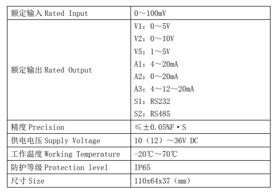
5. Try to use structural accessories with automatic positioning (reset) function, such as spherical bearing, articulated bearing, positioning fastener, etc. They can prevent some lateral forces from acting on the sensor.
6. Handle with care, especially the small capacity sensor made of alloy aluminum elastomer. Any impact and drop may cause great damage to its metering performance.
7. Although the weighing module has a certain overload capacity, the overload of the sensor should be prevented during the installation of the weighing system.
8. In any case, the power line and control line shall be twisted to 50 rpm. If the sensor signal line needs to be extended, a special sealed cable junction box shall be used.
9. Horizontal adjustment: horizontal adjustment has two aspects. First, the installation plane of the installation base of a single sensor should be adjusted horizontally with a level gauge. On the other hand, the installation surface of the installation base of multiple sensors should be adjusted to a horizontal plane as much as possible (with a level gauge), especially in the weighing system with more than three sensors.
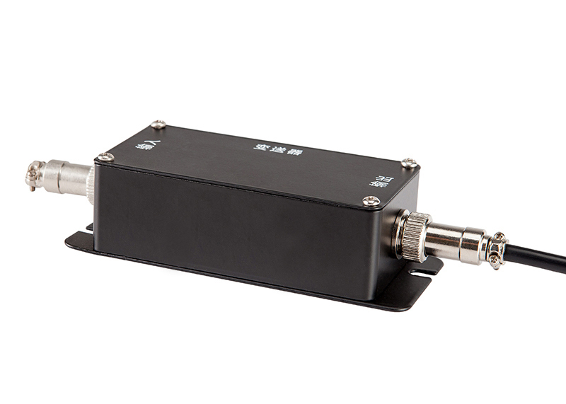
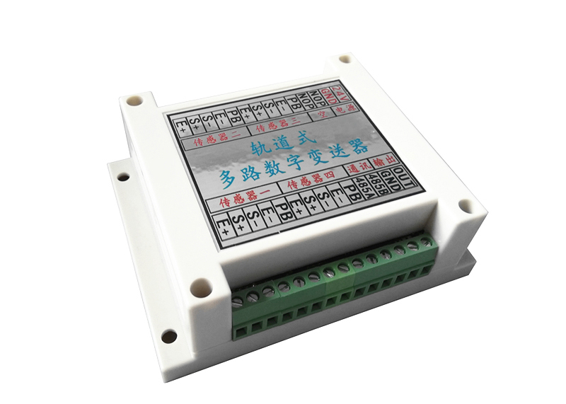
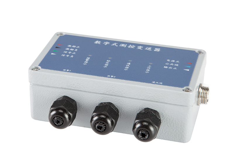
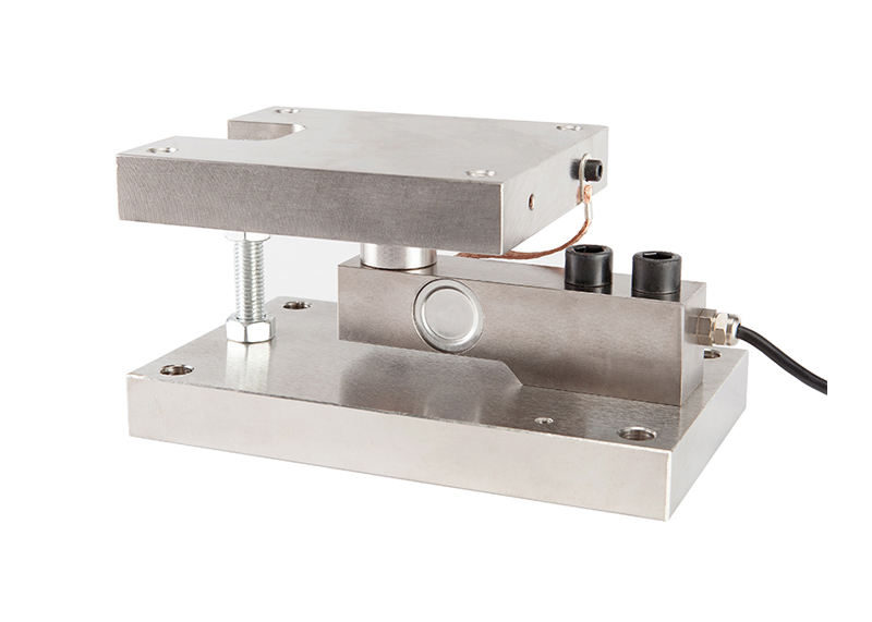
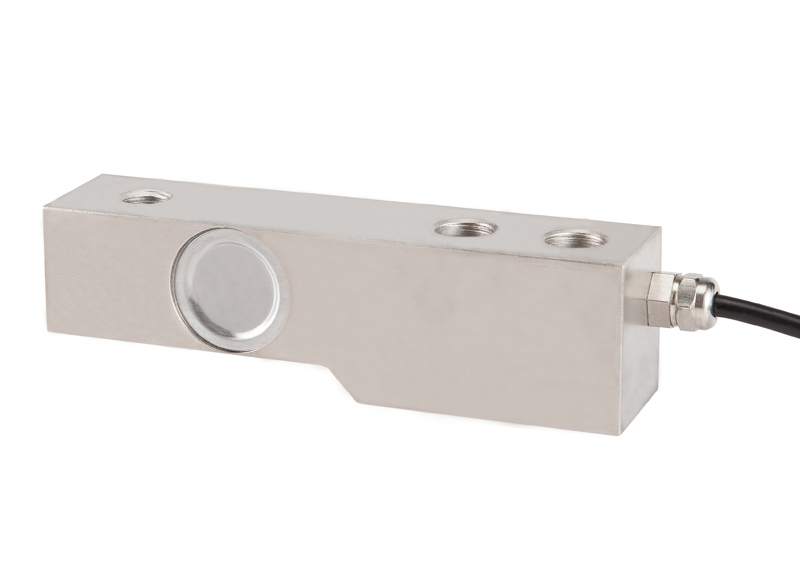
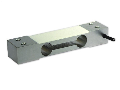
Cantilever sensors are widely used in small Weighbridge and platform scale. Generally, three sensors or four sensors are used as a group. Through the signal and conditioner, the signals of multiple sensors are processed and then transmitted to the measuring instrument, so as to show the measured values.
10. The signal cable of the sensor shall not be arranged in parallel with the strong current power line or control line (for example, do not put the sensor signal line, strong current power line and control line in the same pipe). If they must be placed in parallel, the distance between them shall be kept above 50cm, and the signal line shall be sheathed with metal pipe.
11. In any case, the power line and control line shall be twisted to 50 rpm. If the sensor signal line needs to be extended, a special sealed cable junction box shall be used. If this kind of junction box is not used, but the cable is directly connected with the cable (soldering end), special attention shall be paid to the sealing and moisture-proof. After connection, the insulation resistance shall be checked and meet the standard(2000 ~ 5000m). If necessary, recalibrate the sensor.
12. If the signal cable is very long and high measurement accuracy should be ensured, the cable compensation circuit with relay amplifier should be considered.
13. All conductors leading to or from the display circuit shall be shielded cables. The connection and grounding point of shielding wire shall be reasonable. If it is not grounded through the mechanical frame, it is grounded externally, but the shielding wires are not grounded after they are connected with each other, which is floating.
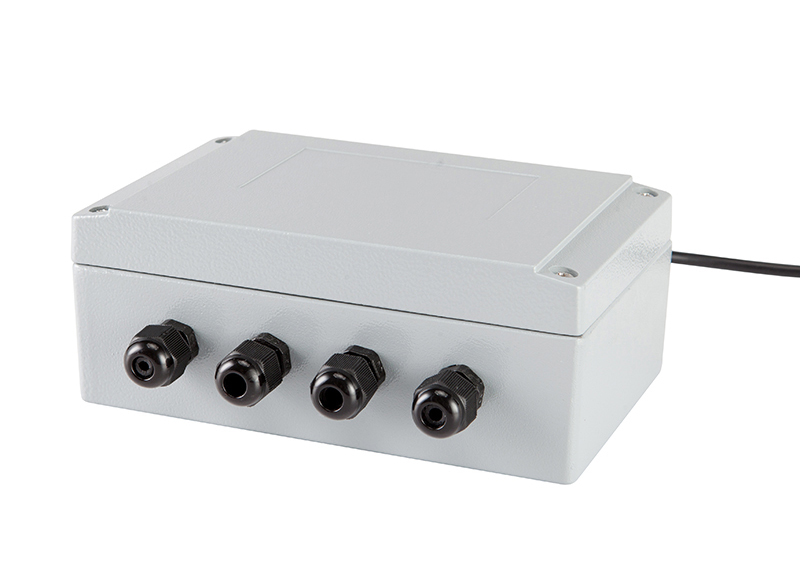
Note: three sensors are connected in full parallel. The sensor itself is a 4-wire system, but it is replaced by a 6-wire system in the junction box.
14. The sensor output signal readout circuit shall not be placed in the same box with the equipment that can produce strong interference (such as "controllable silicon", contactor, etc.) and the equipment with considerable heat generation. If this cannot be guaranteed, it shall be considered to set a baffle between them for isolation, and a fan shall be arranged in the box.
15. The electronic circuit used to measure the output signal of the weight sensor shall be equipped with an independent power supply transformer as far as possible, rather than sharing the same main power supply with equipment such as contactors.

How to preliminarily judge the quality of the sensor?
1. Measure resistance
(1) It would be much easier if there were a manual for the load cell. First use a multimeter to measure the input and output resistance of the sensor, and then compare it with the manual. If the difference is large, it means that the load cell should be retested.

(2) If there is no instruction manual, please measure the input resistance, that is, the resistance between exc + and exc -; Output resistance, i.e. the resistance between sig + and sig -; Input resistance, output resistance and bridge resistance shall meet the following relationship:

(3). Input resistance > output resistance > bridge resistance

(4). The bridge resistances are equal or equal to each other
If you have inconsistent measurement results for several times in a row, you can determine that the sensor is damaged.

2. Measure voltage
First, use a multimeter to measure the voltage between the exc + and exc - terminals of the instrument, which is the excitation voltage of the load cell, including DC5V and dc10v. Here, take DC5V as an example. When no-load, use a multimeter to measure MV between sig + and sig - lines. If it is about 1-2mv, it is correct; If the MV number is particularly large, it indicates that the sensor is damaged.
When loading, please use the multimeter MV file to measure the MV number between sig + and sig - wires. It will increase in proportion to the weight of the load. The maximum value is 5V (excitation voltage) * 2mV / V (sensitivity) = about 10mV. Otherwise, it indicates that the sensor has been damaged.
Common problem
Proposal
Name
Tel
QQ
WeChat
Mailbox
Address
Content
Foshan puliang Electronic Co., Ltd

Tel:0757-26619568 Fax: 0757-26619508

24-hour online technical support:13790092618

Cloud platform:www.puliangiot.com

Address:501, block 8, phase 5, Rongli tianfulai industrial city, Ronggui town, Shunde District, Foshan City

Copyright©Foshan puliang Electronic Co., Ltd