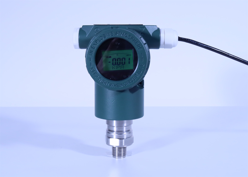
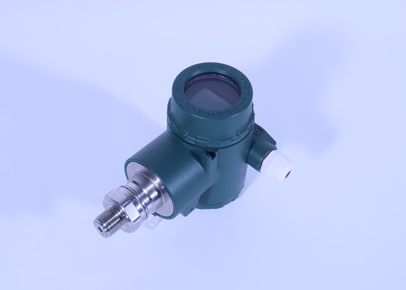
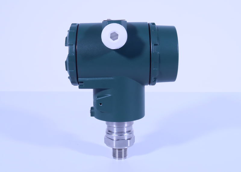
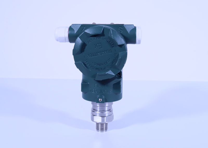
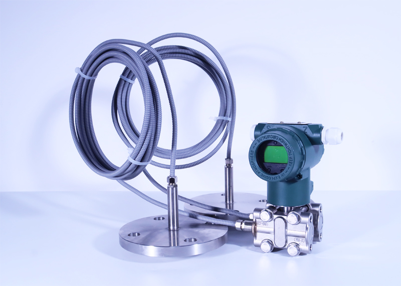
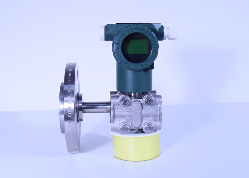
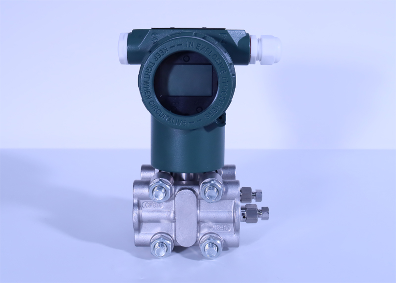
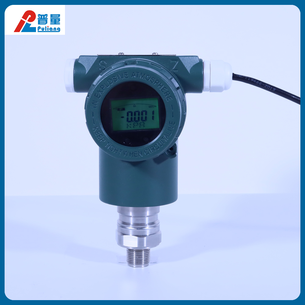
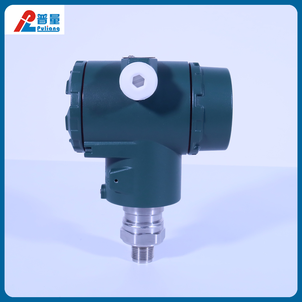
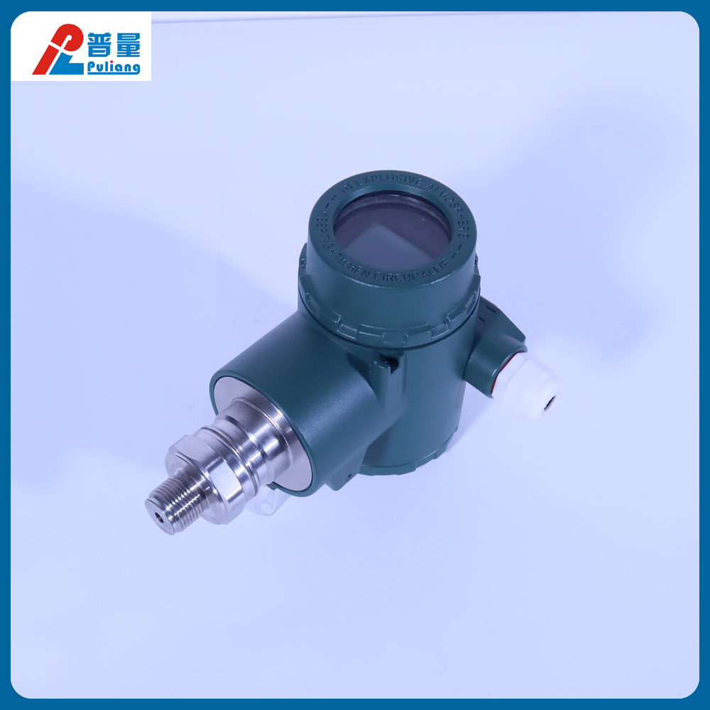
PT500-3351-B GP/AP Single Crystal Silicon High Precision Intelligent Direct Mount Gauge/Absolute Pressure Transmitter
Overview
The PT500-3351 series intelligent pressure/differential pressure transmitter adopts the world's leading high-precision silicon pressure and differential pressure sensor technology and packaging process for the central sensing unit. The monocrystalline silicon pressure and differential pressure sensor is located at the top of the metal body, far from the medium contact surface, achieving mechanical and thermal isolation; The glass sintered sensor leads achieve high-strength electrical insulation with the metal substrate, improving the flexibility of electronic circuits and the ability to withstand transient voltage protection. Platinum grade accuracy reaches ± 0.05%, and one-way overvoltage can reach up to 25MPa. Excellent static pressure performance, with an optimal static pressure error controlled within ± 0.05%/10MPa, minimal temperature variation, and an optimal control of ± 0.04%/10K.
In terms of circuit design, a modular design with a microprocessor as the core and advanced digital isolation technology is adopted, making the instrument highly anti-interference and stable. Using the Hart protocol for communication, remote operation can be carried out through Hart manual operators or computers with Hart software installed to complete measurement information configuration. At the same time, digital compensation technology is adopted, and the transmitter is compensated through built-in temperature sensors, improving measurement accuracy and reducing temperature drift. It has good long-term stability and high reliability. The most user-friendly infrared wireless setting and one click reset function meet the safety operation requirements in hazardous situations, making it very convenient to perform shortcut menu operations and complete all parameter settings, comprehensively improving the performance of the transmitter.
Advantages
◇ Advanced monocrystalline silicon pressure sensor technology and packaging process, meticulously developed an internationally leading ultra high performance pressure and differential pressure transmitter
The modular design with microprocessor as the core and advanced digital isolation technology as auxiliary makes the instrument highly anti-interference and stable
◇ Powerful 24 bit ADC for high accuracy
◇ Innovative dual compensation technology with true 0.075 high accuracy
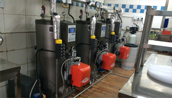
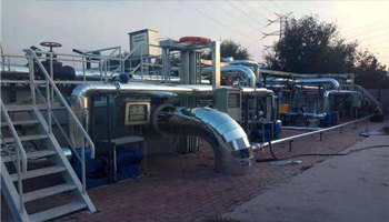
Steam supply system
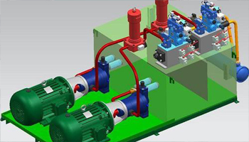
Oil pressure system
petrochemical industry
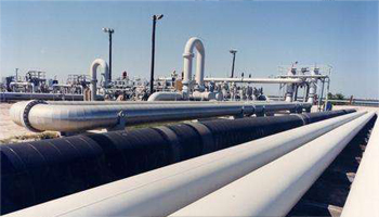
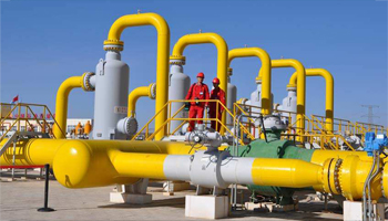
Petroleum Pipeline
Gas supply pipeline
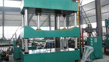
Hydraulic equipment
PT500-3351-B GP/AP 单晶硅高精度智能直装式表压/绝压变送器

2.1.4 Installation precautions
1. Prevent the transmitter from coming into contact with corrosive or high-temperature (≥ 90 ℃) tested media.
2. To prevent sediment from depositing in the pressure pipe.
3. The pressure pipe should be as short as possible.
4. The liquid column pressure heads inside the pressure pipes on both sides of the differential pressure transmitter should be balanced.
5. Pressure pipes should be installed in areas with low temperature gradients and temperature fluctuations.
6. Prevent crystallization or low-temperature freezing in the pressure pipe.
2.2 Issues related to measurement methods Liquid measurement:
When measuring liquid flow rate, the pressure tap should be opened on the side of the process pipeline to avoid sediment. At the same time, the transmitter should be installed next to or below the pressure tap to facilitate the discharge of bubbles into the process pipeline.
Gas measurement:
When measuring gas flow, the pressure tap should be located at the top or side of the process pipeline. And the transmitter should be installed next to or above the process pipeline, so that accumulated liquid can easily flow into the process pipeline.
Steam measurement:
When measuring steam flow rate, the pressure tap should be opened on the side of the process pipeline, and the transmitter should be installed below the pressure tap so that the cold polymer liquid can be filled in the pressure pipe. It should be noted that when measuring steam or other high-temperature media, its temperature should not exceed the operating limit temperature of the transmitter. When the measured medium is steam, the pressure pipe should be filled with water to prevent direct contact between steam and the transmitter. This way, the volume change of the transmitter during operation is negligible, and there is no need to install a condensation tank.
Liquid level measurement:
The differential pressure transmitter used to measure liquid level is actually the static pressure head of the measuring liquid column. This pressure is determined by the height of the liquid level and the specific gravity of the liquid, which is equal to the height of the liquid level above the pressure tap multiplied by the specific gravity of the liquid, regardless of the volume or shape of the container.
⚫ Liquid level measurement of open containers
When measuring the liquid level of an open container, the transmitter is installed near the bottom of the container to measure the pressure corresponding to the height of the liquid level above it. The pressure of the container liquid level acts on the high-pressure side of the transmitter, while the low-pressure side is open to the atmosphere. If the lowest liquid level within the range of measured liquid level change is above the installation of the transmitter, the transmitter must undergo positive migration.
⚫ Liquid level measurement of sealed containers
In a closed container, the pressure P0 of the container above the liquid affects the measured pressure at the bottom of the container. Therefore, the pressure at the bottom of the container is equal to the liquid level height multiplied by the specific gravity of the liquid and the pressure P0 of the closed container. In order to measure the true liquid level, the pressure P0 of the container should be subtracted from the measured pressure at the bottom of the container. To do this, open a pressure tap at the top of the container and connect it to the low-pressure side of the transmitter. In this way, the pressure in the container acts simultaneously on the high and low pressure sides of the transmitter. The resulting differential pressure is directly proportional to the product of the liquid level height and the specific gravity of the liquid.
⚫ Pressure connection method
1) Dry pressure connection
If the gas on the liquid does not condense, the connecting pipe on the low-pressure side of the transmitter remains dry. This situation is called a dry pressure connection. The method for determining the measurement range of the transmitter is the same as the method for determining the liquid level in an open container.
2) Wet pressure connection
If the gas above the liquid condenses, the liquid will gradually accumulate in the pressure pipe on the low-pressure side of the transmitter, causing measurement errors. To eliminate this error, a certain liquid is pre filled into the low-pressure side pressure pipe of the transmitter, which is called a wet pressure connection.
The above situation results in a pressure head on the low-pressure side of the transmitter, so negative migration must be carried out.
Reduce errors
The pressure pipe connects the transmitter and the process pipeline, and transmits the pressure at the pressure tap on the process pipeline to the transmitter. The possible reasons for errors during pressure transmission are as follows:
1) Leakage;
2) Wear loss (especially when using cleaning agents);
3) Gas in the liquid pipeline (causing pressure head error);
4) Accumulation of liquid in the gas pipeline (causing pressure head error); 5) The density difference between the two pressure pipes due to temperature difference (causing pressure head error);
The methods to reduce errors are as follows:
1) The pressure pipe should be as short as possible;
2) When measuring liquid or steam, the pressure pipe should be connected upwards to the process pipeline, and its slope should be less than 1/12;
3) For steam measurement, the pressure pipe should be connected downwards to the process pipeline, and its slope should not be less than 1/12;
4) The layout of liquid pressure pipelines should avoid high points in the middle, and the layout of gas pressure pipelines should avoid low points in the middle;
5) The two pressure pipes should maintain the same temperature;
6) To avoid friction effects, the diameter of the pressure pipe should be large enough;
7) There should be no gas present in the liquid filled pressure pipe;
8) When using isolation liquid, the liquid in both pressure pipes should be the same;
9) When using cleaning agents, the connection of the cleaning agent should be close to the pressure tap of the process pipeline. The length and diameter of the pipeline through which the cleaning agent passes should be the same, and the cleaning agent should be avoided from passing through the transmitter.
2.5 Description of Flameproof Transmitters
When installing an explosion-proof transmitter, attention should be paid to protecting the explosion-proof joint surface and taking explosion-proof measures. The end cover must be screwed to the bottom and the anti loosening device must be locked; The shell should be grounded; When loading and unloading parts with flat gaps, it is necessary to prevent flat collisions and scratches from increasing the gap; The shell should be prevented from falling, colliding, or damaging to avoid reducing its strength; After the maintenance and inspection of the instrument, all screws, shells, and wiring must be tightened and not damaged, otherwise the explosion-proof performance will be lost.
Explosion proof transmitters are strictly prohibited from opening or loosening the end cover or casing when powered on on-site.
The two outlet ports of the explosion-proof transmitter should be wired with one of the inlet cables, and the cable joint should use a dedicated compression nut type explosion-proof inlet device. The tightened hollow bolt, washer, and sealing rubber ring should be wrapped around the outer diameter of the cable, installed into the interface and tightened. The sealing ring must ensure that it is tightly wrapped around the outer diameter of the cable, and the hollow bolt must be screwed in more than 6 threads. The other outlet must also be equipped with a sealing rubber ring, washer, and solid bolt, which must be tightened and screwed in more than 6 threads. To meet explosion-proof requirements, cables with a diameter of 1.5 * 4 cores and an outer diameter of 10mm (10.5mmMAX) should be selected.
The structure and components of the explosion-proof transmitter have been strictly inspected and tested according to the explosion-proof standard, and comply with the provisions of the national standard GB3836.2-2000 "Explosion proof Electrical Equipment for Explosive Atmospheres" d ". Its symbol is EXds Ⅱ BT5.
Tel:0757-26619568 Fax: 0757-26619508
24-hour online technical support:13790092618
Cloud platform:www.puliangiot.com
Social networks: